Closed Loop Control for a Novel Steerable Surgical Needle
A stereo computer vision system that follows a tape-spring steerable needle through gel, built at Penn's GRASP Lab (ModLab) with Prof. Mark Yim.
Role
Graduate Student Researcher
Industry
Surgical Robotics
Duration
4 Months

Overview
The Modular Robotics Lab (ModLab) at Penn's GRASP Lab, led by Prof. Mark Yim, is building a steerable needle that can turn sharply inside tissue. My main contribution is the computer vision system that tracks the needle's tip through gel in 3D. I also worked on the needle's math model and led the experiments that tested it.
At a glance…
1 to 3 tracked points on the needle, enough for position and orientation
2 cameras in stereo, with a Snell's law correction for light bending through gel
0.9 mm mean error in the needle's kinematic model across 82 measured tip positions (team result)
About 7 mm to under 1 mm depth error through gel after the refraction correction
2 versions of a custom laser-cut gel box
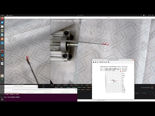
Live tracking of three red dots on the needle, with its 3D position and orientation plotted beside the camera view.
Straight Needles Cannot Reach Every Target
Biopsies and targeted radiation, such as lung and liver biopsy and prostate brachytherapy, depend on reaching a precise spot
A straight needle limits what it can reach, because it cannot go around obstacles
Existing steerable needles turn gradually, which also limits where they can go
ModLab's tape-spring needle (Abdoun et al., Penn Engineering and Perelman School of Medicine) is designed to make sharp turns through tissue
A Needle That Buckles to Turn
A tape spring is a thin curved metal strip: stiff enough to push through tissue, and able to buckle on command to turn
Cables pull the tip to steer it
ModLab's 2D needle turned in one plane. A new cable routing, crossing an active and a passive cable, lets the 3D version steer out of plane
Crossed cable routing lets the needle steer in 3D
A Model That Predicts Where the Tip Goes
I worked with labmate Qiwen Ding on a kinematic model that turns cable pulls into tip positions
It treats the front of the needle as rigid and the bend as a constant curve, in a straight, curved, straight shape
Checked against 82 measured tip positions, the model's mean error was 0.9 mm (max 1.9 mm)
Checking it takes a measurement of the real tip in 3D, which is where the vision system comes in

Mathematical model derivation, assuming quasi-static behavior.
A Test Rig for Needle Experiments
Stepper motors pull the cables and push the needle forward, driven by an ESP32 and motor drivers
A collar keeps the needle from twisting
Two cameras watch the needle move through gel, which stands in for tissue
I led the experiments: inserting the needle in air and gel, steering it, and capturing the tip with the stereo cameras

The test rig: control circuitry (left), motors and needle (center), and the stereo cameras watching a gel block (right).
Computer Vision: Teaching the System to See the Needle
The existing tracker followed one red dot with color filters and background subtraction. It needed retuning whenever the lighting changed and could not follow more than one point. I rebuilt it in stages with ROS, Python, and OpenCV.
Motion says where to look. Color says what to look at. Stereo says how far away it is.
Stage 1. Choose a marker that stands out
I tested colored nail-polish dots on the needle
Green blended into the gel, and red stood out clearly
Testing marker colors in gel: the red dot stays visible and the green one blends in.
Stage 2. Keep detection working as the light changes
The original HSV color filter broke down when the light changed or the gel fractured
I switched to a YCrCb filter, which separates redness from brightness
An early tracker with motion prediction scored perfectly on recorded video but failed on live cameras, so I tested on the live system from then on

Unlike HSV, the YCrCb color filter is designed to isolate brightness which makes our tracking more robust in varied lighting conditions.
Stage 3. Track three points, not one
One dot gives the tip's position. Three dots give its position and orientation (full 6-DOF)
All three dots are red, so the system tells them apart by their fixed spacing, not color
If one dot is briefly hidden, the system places it from the other two

Three tracked dots, numbered 1 to 3, in two camera views.
Stage 4. Calibrate the cameras so the 3D numbers can be trusted
I rebuilt stereo calibration around a checkerboard method, replacing the earlier AprilTag approach
Squares of known size gave a check on the 3D results
Stage 5. Correct for light bending through gel
Cameras viewing at an angle through gel see the tip in the wrong place, and the error grows as the needle goes deeper
I measured how strongly the gel bends light, about 1.35 at two setup positions (1.345 and 1.350), and applied Snell's law to correct each camera's view
In bench tests, depth error through the gel fell from about 7 mm to under 1 mm

Light bends at the gel surface, so the triangulated tip (gray) sits shallower than the true tip (orange).
A Better Gel Box
Looking straight through a wall bends light less, so I designed a laser-cut acrylic box with a removable side wall
Version 1: finger joints and solvent welding still leaked, and demolding tore the gel next to the removable wall
Version 2: waterproof caulk sealed the removable wall, tape stopped the leaks, and cutting the gel free with a box cutter cut breakage considerably

Version 1: laser-cut acrylic with finger joints, solvent-welded, and the torn gel near the removable wall.

Version 2: sealed removable wall, taped seams, and cleaner demolding.
Putting It Together: Steering in Air and in Gel
We ran the same cable commands in air and in gel and tracked the tip with the vision system
The needle turned in gel much like it did in air, a promising proof of concept
Making the result stable and repeatable is the next step
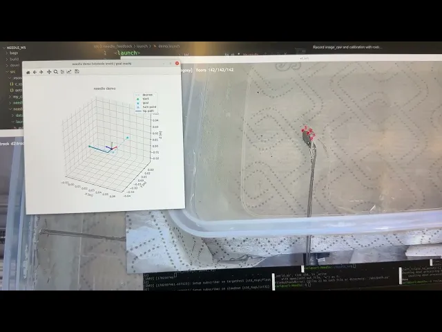
Steering in gel, with the tracked dots and the planned path shown in the plot.
Challenges That Shape the Next Steps
Markers change the needle. The dots that make tracking possible dull the edge they sit on, a tradeoff between visibility and sharpness
Gel and light are hard on vision. Gel cracks into shards that hide dots, and bright light washes them out
Refraction still matters. The correction is software, and the box wall reduces it by design

Dots on one edge of the needle tip (top arrow) make it duller than the clean edge (bottom arrow).
Next Steps
Scale up the open-loop experiments
Close the loop: use the live tip position to correct the needle's path as it moves. In simulation, a model-based feedback controller brings the tip within 0.1 mm of a goal in about a dozen steps
Verify the model on the opposite steering side
Improve vision: test how much refraction error matters in practice, and rely less on large physical markers

Simulation: a feedback controller steering the model needle's tip to a goal (left) with the error shrinking each step (right).
Three Things I Took From It
Fix the physical problem before the algorithm. Marker color, camera angle, and the gel box changed what the software had to solve.
Trust live results over recordings. A tracker that looked perfect on recorded video failed on live cameras, so I test on the live system first.
Make the measurement trustworthy before using it. Calibrating the cameras and correcting for refraction came before any conclusion about the needle.
Credits: Modular Robotics Lab (ModLab), GRASP Lab, Penn Engineering. PI: Prof. Mark Yim. Team: Qiwen Ding, Xiaohan, Nicole, Mahika, Eric. Triangulation and the 3D display were built together with ModLab teammates. Builds on the lab's 2D tape-spring needle by Abdoun, Tjandra, Yin, Kurzan, Yin, and Yim. This is ongoing research and results are preliminary.
Overview
The Modular Robotics Lab (ModLab) at Penn's GRASP Lab, led by Prof. Mark Yim, is building a steerable needle that can turn sharply inside tissue. My main contribution is the computer vision system that tracks the needle's tip through gel in 3D. I also worked on the needle's math model and led the experiments that tested it.
At a glance…
1 to 3 tracked points on the needle, enough for position and orientation
2 cameras in stereo, with a Snell's law correction for light bending through gel
0.9 mm mean error in the needle's kinematic model across 82 measured tip positions (team result)
About 7 mm to under 1 mm depth error through gel after the refraction correction
2 versions of a custom laser-cut gel box
Live tracking of three red dots on the needle, with its 3D position and orientation plotted beside the camera view.
Straight Needles Cannot Reach Every Target
Biopsies and targeted radiation, such as lung and liver biopsy and prostate brachytherapy, depend on reaching a precise spot
A straight needle limits what it can reach, because it cannot go around obstacles
Existing steerable needles turn gradually, which also limits where they can go
ModLab's tape-spring needle (Abdoun et al., Penn Engineering and Perelman School of Medicine) is designed to make sharp turns through tissue
A Needle That Buckles to Turn
A tape spring is a thin curved metal strip: stiff enough to push through tissue, and able to buckle on command to turn
Cables pull the tip to steer it
ModLab's 2D needle turned in one plane. A new cable routing, crossing an active and a passive cable, lets the 3D version steer out of plane
Crossed cable routing lets the needle steer in 3D
A Model That Predicts Where the Tip Goes
I worked with labmate Qiwen Ding on a kinematic model that turns cable pulls into tip positions
It treats the front of the needle as rigid and the bend as a constant curve, in a straight, curved, straight shape
Checked against 82 measured tip positions, the model's mean error was 0.9 mm (max 1.9 mm)
Checking it takes a measurement of the real tip in 3D, which is where the vision system comes in
Mathematical model derivation, assuming quasi-static behavior.
A Test Rig for Needle Experiments
Stepper motors pull the cables and push the needle forward, driven by an ESP32 and motor drivers
A collar keeps the needle from twisting
Two cameras watch the needle move through gel, which stands in for tissue
I led the experiments: inserting the needle in air and gel, steering it, and capturing the tip with the stereo cameras
The test rig: control circuitry (left), motors and needle (center), and the stereo cameras watching a gel block (right).
Computer Vision: Teaching the System to See the Needle
The existing tracker followed one red dot with color filters and background subtraction. It needed retuning whenever the lighting changed and could not follow more than one point. I rebuilt it in stages with ROS, Python, and OpenCV.
Motion says where to look. Color says what to look at. Stereo says how far away it is.
Stage 1. Choose a marker that stands out
I tested colored nail-polish dots on the needle
Green blended into the gel, and red stood out clearly
Testing marker colors in gel: the red dot stays visible and the green one blends in.
Stage 2. Keep detection working as the light changes
The original HSV color filter broke down when the light changed or the gel fractured
I switched to a YCrCb filter, which separates redness from brightness
An early tracker with motion prediction scored perfectly on recorded video but failed on live cameras, so I tested on the live system from then on
Unlike HSV, the YCrCb color filter is designed to isolate brightness which makes our tracking more robust in varied lighting conditions.
Stage 3. Track three points, not one
One dot gives the tip's position. Three dots give its position and orientation (full 6-DOF)
All three dots are red, so the system tells them apart by their fixed spacing, not color
If one dot is briefly hidden, the system places it from the other two
Three tracked dots, numbered 1 to 3, in two camera views.
Stage 4. Calibrate the cameras so the 3D numbers can be trusted
I rebuilt stereo calibration around a checkerboard method, replacing the earlier AprilTag approach
Squares of known size gave a check on the 3D results
Stage 5. Correct for light bending through gel
Cameras viewing at an angle through gel see the tip in the wrong place, and the error grows as the needle goes deeper
I measured how strongly the gel bends light, about 1.35 at two setup positions (1.345 and 1.350), and applied Snell's law to correct each camera's view
In bench tests, depth error through the gel fell from about 7 mm to under 1 mm
Light bends at the gel surface, so the triangulated tip (gray) sits shallower than the true tip (orange).
A Better Gel Box
Looking straight through a wall bends light less, so I designed a laser-cut acrylic box with a removable side wall
Version 1: finger joints and solvent welding still leaked, and demolding tore the gel next to the removable wall
Version 2: waterproof caulk sealed the removable wall, tape stopped the leaks, and cutting the gel free with a box cutter cut breakage considerably
Version 1: laser-cut acrylic with finger joints, solvent-welded, and the torn gel near the removable wall.
Version 2: sealed removable wall, taped seams, and cleaner demolding.
Putting It Together: Steering in Air and in Gel
We ran the same cable commands in air and in gel and tracked the tip with the vision system
The needle turned in gel much like it did in air, a promising proof of concept
Making the result stable and repeatable is the next step
Steering in gel, with the tracked dots and the planned path shown in the plot.
Challenges That Shape the Next Steps
Markers change the needle. The dots that make tracking possible dull the edge they sit on, a tradeoff between visibility and sharpness
Gel and light are hard on vision. Gel cracks into shards that hide dots, and bright light washes them out
Refraction still matters. The correction is software, and the box wall reduces it by design
Dots on one edge of the needle tip (top arrow) make it duller than the clean edge (bottom arrow).
Next Steps
Scale up the open-loop experiments
Close the loop: use the live tip position to correct the needle's path as it moves. In simulation, a model-based feedback controller brings the tip within 0.1 mm of a goal in about a dozen steps
Verify the model on the opposite steering side
Improve vision: test how much refraction error matters in practice, and rely less on large physical markers
Simulation: a feedback controller steering the model needle's tip to a goal (left) with the error shrinking each step (right).
Three Things I Took From It
Fix the physical problem before the algorithm. Marker color, camera angle, and the gel box changed what the software had to solve.
Trust live results over recordings. A tracker that looked perfect on recorded video failed on live cameras, so I test on the live system first.
Make the measurement trustworthy before using it. Calibrating the cameras and correcting for refraction came before any conclusion about the needle.
Credits: Modular Robotics Lab (ModLab), GRASP Lab, Penn Engineering. PI: Prof. Mark Yim. Team: Qiwen Ding, Xiaohan, Nicole, Mahika, Eric. Triangulation and the 3D display were built together with ModLab teammates. Builds on the lab's 2D tape-spring needle by Abdoun, Tjandra, Yin, Kurzan, Yin, and Yim. This is ongoing research and results are preliminary.
Other projects

Hand Hygiene Reminder Light for Central Line Care at CHOP
A battery-powered light that reminds nurses to clean their hands before central line care, developed through five prototypes with Children's Hospital of Philadelphia nursing teams.

Imitation Learning on a 6DoF Robot Arm: Peg Transfer
An independent project: collecting demonstrations on an SO-101 arm and comparing ACT, Diffusion Policy, and SmolVLA on a peg transfer task inspired by surgical training.

Cup Tracking for a Multi-Robot Trail Mix Line
Building a ROS vision module that tells four robot arms where every cup is, from AprilTag detection to a full live demo.
Autonomous Car
Designing and building an autonomous mobile robot with real-time control, localization, and sensing, from system architecture to competition-ready deployment.
Biofluid Analyzer
Developing a compact bedside urine output monitoring system for critical care, from clinician pain point to deployed prototype and formal pilot study.
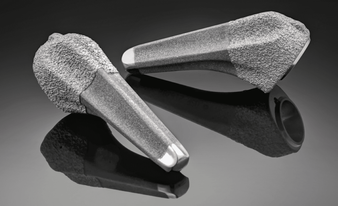
Orthopedic Product Development at Exactech
Led surgeon-driven instrument and implant development across CAD, DFM, testing, manufacturing, and 510(k) support through 7 concurrent projects.
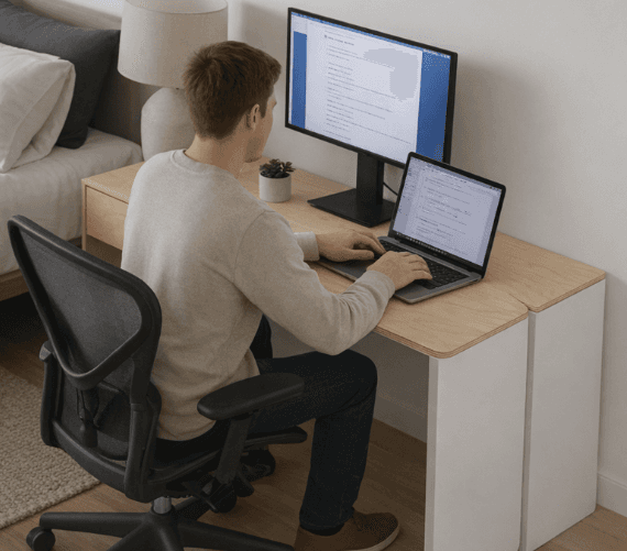
Arco: Transformable Desk for Small-Space Living
Arco is a configurable desk system designed for students living in small spaces, created to help people physically and mentally transition between modes throughout the day.

Product Growth at PrimeEventZ
Leading product definition and real-world deployment of PrimeEventZ, an AI-powered platform unifying event operations from planning through execution at any scale.